
Security Alarm Systems
ST-AS102G/GSM Security Alarm System
ST-AS10: ABS construction. Review the complete technical data and system connections below.
- Display
- 4.3 Inch LCD Touch Screen
- Power Supply
- 5V-1A
- Material
- ABS
Overview
ST-AS10 is a security alarm panel for supported sensors and incident notifications. Review connectivity, sensor capacity, display, mounting and electrical requirements for the intended property.
Plan network connectivity, operator workflow, mounting and power as part of the complete communication system. Explore the application guides for deployment considerations.
Key features
- Easy & Effective operations
- 2G/GSM/Wi-Fi
- Support Wireless Sensors
- Support Smart Life/Tuya App
- Can work with IP Products
- High-definition touch screen: 4.3 inches LCD
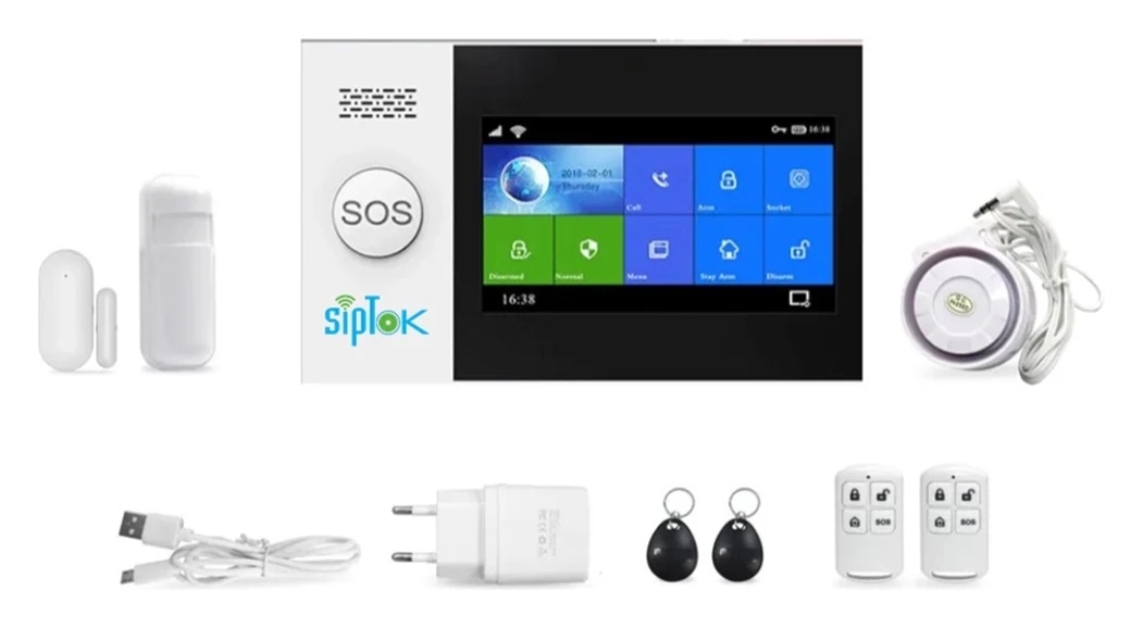
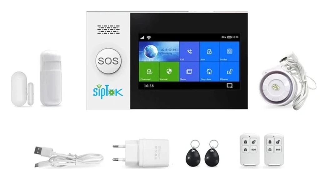
- Package includes 02 RFID Tags, 02 Remotes, 01 Door Sensor, 01 PIR Sensor, 01 Hooter
Technical specifications
ST-AS10| Parameter | Specification |
|---|---|
| Sensors | |
| RFID Tag | 02 |
| Remote | 02 |
| Door Sensor (wireless) | 01 |
| PIR Sensor (wireless) | 01 |
| Hooter (wired) | 01 |
| Sensors | |
| Wi-Fi Standards | IEEE 802.11 b/n/g 2.4 GHz |
| 2G/GSM Freq. | 850/900/1800/1900 MHz |
| Wireless Freq. | 433 MHz |
| Wireless Transmission Range | 100 meters (open area) |
| Support Wireless Detector, RFID tags | Max. 100 pcs |
| Support Wire Zones | 4 pcs |
| Alarm Call/SMS Number | 5 Groups |
| Two-way audio | 2G/GSM Support |
| Timing Control | Arm/Home Arm/Disarm |
| General | |
| Mobile App | Smart Life/Tuya |
| Support Voice Control | Amazon Alexa, Google Assistant |
| Material | ABS |
| Display | 4.3 Inch LCD Touch Screen |
| Color | White |
| Power Supply | 5V-1A |
| Sound Level | 100dB |
| Installation | Wall Mount |
| Dimensions | 160x98x19 mm |
| Net Weight | 500 gm |
| Languages | English |
| Standard Warranty | 1 year |
| Approvals & Compliances | ISO 9001:2015, ISO 27001:2022, CE, RoHS, FCC |
| Package Includes | 2G/GSM Security Alarm Panel, 02 RFID Tags, 02 Remotes, 01 PIR Sensor, 01 Door Sensor, 01 Wired Hooter, 01 Adapter, 01 User Manual |
Confirm the required configuration and current product documentation before procurement.
Product documentation
Product documents are available to approved SipTok partners and invited project teams.
Partner document accessSYSTEM CONNECTIONS
Where ST-AS10 fits.
A dedicated sensor and incident-notification path. Security alarm panels form a separate system from SIP paging and emergency calls.
SIPTOK · SCHEMATIC DIAGRAM
ST-AS10 in a security alarm installation

Sensor signal / configured serviceAnalogue audio / wired outputSelect a product photograph for model details
Scroll across the diagram to explore each connection.
Compatible wireless sensorDoor sensorConfigured sensor connection
Compatible wireless detectorPIR sensorConfigured sensor connection
Local audible notificationWired hooterConfigured notification output
Model-supported notification routeConfigured phone / appConfigured notification output
01
Detection to local alert
A configured sensor event is handled by the alarm panel and can activate its supported local notification outputs.
02
Remote notification
Set up the model-supported mobile or app service and the intended recipients. Cellular service and network coverage are separate site requirements.
Connection, power & commissioning notes
- The alarm panel is not shown as an IP PA controller. A statement that it can work with IP products does not identify a universal SIP or fire-alarm interface.
- Verify sensor pairing, wired connections, power, communications service and incident response procedures for the selected model.
Photographs show actual SipTok models. This is a conceptual connection diagram; cable routes, power and final equipment are confirmed during system design.
APPLICATIONS
Where ST-AS10 fits.
Explore the operating environment and communication requirements for each use case.
 Retail & Shop Security
Shop & retail security
Plan door and movement detection, authorized users and the intended incident-notification route.
Explore the solution Commercial Buildings
Commercial premises
Pair the supported sensors and define arming, disarming and response responsibilities for the property.
Explore the solution Warehouses & Logistics
Stores & support premises
Review wireless sensor coverage, power and notification service in the actual building before commissioning.
Explore the solutionPRODUCT SELECTION & INSTALLATION
Questions about ST-AS10.
Review the model’s connection, installation and documentation before finalizing the system.
Ask a product expertWhat power arrangement is listed for ST-AS10?
The published power-supply field states “5V-1A”. Check the installation supply and the current model document.
How is ST-AS10 installed?
The published installation field states “Wall Mount”. Confirm the mounting surface, clearances, cable route and environmental requirements for the site using the current model documentation.
What should I include in a ST-AS10 enquiry?
Include the model, quantities, site layout, intended workflow and connected equipment. For a complete system, share paging zones, network and power availability, and any BOQ, RFP or configuration support required.
EXPLORE THE RANGE
Related products.
LET’S START A CONVERSATIONDiscuss your
Discuss your
IP PA project.
From product selection to system planning, share your requirements with the SipTok team.
Explore project engineering supportEmail our teamsales@siptok.in
WhatsApp+91 8590528734
Registered address & manufacturing unitN-189, Pocket N, Sector 2, DSIIDC, Bawana Industrial Area, Delhi – 110039, India